This is version 1.9, not indicating that the tutorial has made a big
step forward (it has not) but it seemed like a nice number to end my involvement
in the scenery tutorial. That means, that unless some major breakthrough
is discovered, you are looking at the final version of this document. If
you don't like that, or want to notify me of something concerning this
tutorial, contact me at m.p.j.keizer@sepa.tudelft.nl
Index
Introduction1) Scenery Basics
2) Commands Overview
3) Guideline
4) Basic Structures
5) addie's special-request section
Appendix
Introduction
By Martijn Keizer, m.p.j.keizer@sepa.tudelft.nlIn this document, I will try to share the knowledge I accumulated over the last months about the editing of GP2-scenery structures.
Therefore I would like to start with some theoretical basics you have
to know about when trying to understand what I try to make clear. Then,
an overview of the commands used while editing scenery, from Addie’s Command-library,
supplemented by some practical tips concerning the use of these commands.
This is followed by a step- by -step guideline how to build the scenery.
In chapter 4 I made some drawings of basic structures and formations as
examples of scenery-editing. The appendix contains some things I couldn't
place elsewhere, like a FAQ and version updates. But first:
Credits
A lot of thanks go to Paul Hoad, for the editor and lots of support. When I heard there was gonne be a Trackeditor, I started making drawings of circuits etc, and finally I decided that it was time to replace the 486 anyhow. This editor has had a lot to do with that! So I guess the registration fee was only a very marginal addition to the costs of making tracks.Also credits to addie, for finding the basics about scenery editing (amongst other subjects as pilanes etc.), and taking the time to write it down in the command-library, pitlane-tutorial and GP2-trackediting tutorial. Without him, command 0xB8 would still be unknown!
I would also like to thank everyone who found out thinks for GP2, it
becomes even more clear you can't do it all yourself. The funny thing is,
you don't have to! So I use sometimes pieces of information that are not
originally my own finding, but rather combinations of different sources
and quick notes by someone, that I tried to take together in a comprehensive
and easy-to-read form. So when you think your name should be explicitely
called in this tutorial, let me know, and I'll add you to the following
list of contibuters!
John Verheijen, Swervin' Irvin', Snqqpy.dog, Glenn Durden, Michael
Hompus, Babbel, Bob Culver, Jason Sinnbeck,
And of course to all trackeditors that keep making even-better-looking
tracks. On one hand I really hate that, because it costs so much more time
to make a decent track relative to others! But I really hope this tutorial
helps all trackeditors to enhance their tracks to a next "generation".
Tracks:
In this tutorial I will sometimes point to a track, where there can be found a good example of the effects I wanted to describe. These tracks are mainly the original tracks of Monaco and Spa-Francorchamps, together with two tracks I build myself as an exercise and experiment for using scenery. These tracks are StuwLake Track, and Tunneltrack. These two tracks are available for download at GP2.com and at Sjons GP2 site. You may wish to take a look at these tracks, in order to get some idea of the possibilities of scenery.Chapter 1
Scenery Basics
In this chapter I will guide you through the different sets of coordinates GP2 uses, and the basic structure of any scenery-piece. Therefore, first a description of the "ribbon"-concept will be given, then some beautiful drawings by Addie to explain the coordination system along with some notes.1.1 Ribbons
Have you ever build a mountain for your little model-train? One way to do this is to build a framework of iron-wire, and then glue some heavy paper over the framework. Well, in GP2 the scenery is build in a similar way. The Scenery1 (0xB8) command defines the basic framework. It consists of four places where the paper can be attached to. These arms are always in the plane perpendicular to the axis of the track. Now these strips of paper are called "RIBBONS" in GP2-terminology.1.2 Banks
The space between the fences and the lower ribbons is also filled with a texture. We will call these textures "BANKS" in GP2. If you press alt-D two times in the game, you will see that all "ribbons" disappear, but the "Banks" stay. This way, you can clearly see what is "bank" and what is "ribbon".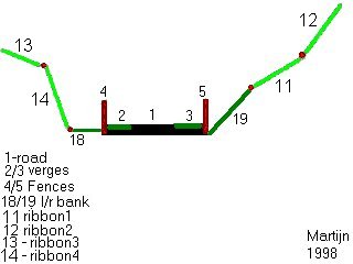
1.3 Coordination System
The precise places of where the ribbons are, is defined by the Scenery1 (0xB8) command. The arguments of this command are the coordinations of the connection places relative to the local tracksection. Thus, every tracksection has its own relative system, and a ribbon at a height of 1000 in two consecutive tracksections will be parallell to the track, regardless of the height-change of the actual tracksection.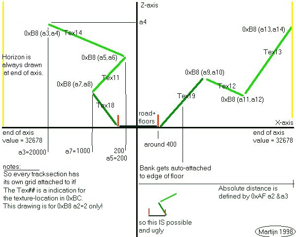
X - axis
The zero-value for the x-direction is the middle of the road. Positive values are to the right, and negative values for the X’s of the ribbons are to the left side of the track. The maximum value is 32767, the highest integer value. You can make ribbons anywhere you like. That means, you can make the ribbons start at the side of the track, or halfway a gravel trap. Normally, this is very ugly. So for most uses, the ribbons are OUTside the fences. So you will have to use a minimum value of about 600 to both sides for X-value. But the exact X-value of the fences in this coordination system is determined by the "trackwidth" and the width of the verges. So you will have to try and experiment a little.Z-axis
The zero-value for the Z-direction is the surface of the road. So a positive value is higher, and a negative value is lower than the road. The height of the fence is approx. 200, as a indication. For trees along the road, a value of about 4000 looks good.1.4 Horizon
As I said, the maximum X-value of a ribbon is 32767. This value means that the ribbon is attached to the "horizon". So you should see every X-value as a "relative place" of the ribbon between the horizon and the middle of the road.Now, the "real" distance from the middle of the road to the horizon
is determined by the Scenery 3 (0xAF) command. So if you increase the values
of this command, the whole scenery becomes more "stretched". If you decrease
this value, the whole scenery becomes more "dense", and the horizon will
appear to be closer to the track. A "normal" value for this command
is 16384, and in most original GP2 tracks, the value for this command differs
too little from this to notice anything.
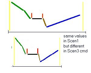
The values for Scen1 are the same in both situations, the values for
Scen3 are halved. The black line is the road, the red the armco, the green,
brown and blue are
ribbons and the position for the vertical yellow line, the horizon,
is definened by Scen3. As you can see, just decreasing the values in Scen3
makes the whole
scenery more "dense".
1.5 Number of ribbons to a side
Normally in a standard situation, there are two ribbons to the right and two to the left. It is however possible to change this situation. In some cases it is useful to have three ribbons to one side, or even four. Because the number of total ribbons is maximized to four, a ribbon added to the right is subtracted from the left side. The a2 of the Scenery1 (0xB8) command determins the "number of ribbons to the right".Note that if you change the Scenery1 (0xB8) a2 value in the middle of your track, that a ribbon has to cross the track. That gives sometimes an ugly scenery flash. Therefore you have to switch the ribbons off temporarily. How to do that will be explained later.
In this document I normally presume, for most cases, that the ribbons
are equally distributed. Otherwise it will be explicitely announced.
1.6 Naming the ribbons
A ribbon is totally useless without a texture applied to it. It is important to know where ribbons are if you want to select textures for the ribbons. So I have taken the terms used in the 0xBC command as a guideline to name the ribbons.Because the ribbons can show up on any side, I will try to explain the numbering with the following drawing.
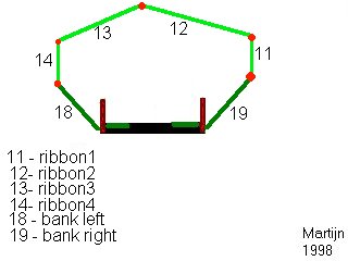
Imagine a tunnel. You see that the ribbons are numbered consecuative. Note that it is NOT necesarry to know in this case how many ribbons come from the right, and how many from the left. So look at a2, number of ribbons to the right, as a determination of WHERE these ribbons are cut into a number to the left and a number to the right. If you remember this picture, you will also be able to see easily why you have to rotate the texture on ribbons to the left, and not on the right.
So from right-down to left-down we find the texture-location values: "19,11,12,13,14,18".
If there’s a "cut" in the middle ("2") then the right side constitues of (from bottom) rightbank (19), ribbon1 (11) and ribbon2 (12). The left side constitues of (from bottom) leftbank (18), ribbon4 (14), ribbon3 (13).
In the case there’s a value (Scenery1 (0xB8) a2=3), then the rightside consistets of rightbank (19); ribbon1 (11); ribbon2 (12); ribbon3 (13). The leftside is (f.b.) leftbank (18); ribbon4 (14);
I expect you will see the logic in this, and work the other situations
out yourself.
1.7 Pitlane Scenery
As you may have noticed in browsing through some tracks, all tracks have Pitlane-scenery commands. However, they are in most tracks disabled and thus not visible in the game. Ofcourse there is a exception to this rule, it being Monaco. The pitbuilding there is constructed from a ribbon, with a garage-texture applied to it. As you probably have NOT noticed, these pit-ribbons are INvisible when you are driving on the main road. Therefore, the usefulness of this pitscenery is reduced to some very special cases. I can think of, for instance, a way to make those pitwall-tents where Ron Dennis and Jean Todt watch the race. You know, the kind of tents that Jos Verstappen likes to smash [France 1994]. You may think of other uses yourself, if you can...If you want to know, the pitlane-scenery is enabled by placing a 0xD9 command with a2=63, at the first pit-scenery command.
You could however also use the main scenery-ribbons to make a pitbuilding
that is visible from the pitlane as well as from the main straight. Therefore,
you must enable the ribbons near the start/finish-area, and make the ribbons
start at the edge of the pitlane-road. You can (for instance) make pitboxes
that seem to be carved out of a high rock. An example of the use of pitlane
scenery can be found on the "StuwLake" track.
1.8 Two sides to all Ribbons
Note that a ribbon has two sides: a front and a back site. Looking onto the front, you see a texture. Looking onto the back of a ribbon, it is completely transparent. Bear that in mind when trying to develop complex scenery structures, as sometimes the ribbons are bended in such a way that they become totally invisible. Imagine a tunnel, like in section 1.6. Now, driving from the track, you can see all ribbons. But when you have a camera outside of the tube, you won't see any ribbons at all.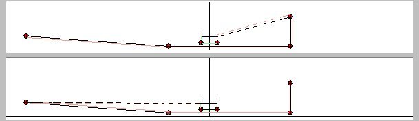
Here you see two different solutions to the same problem. The aim is
to build a bridge. Both setups are with three ribbons to the right. On
top you see that the visible side of the ribbons (marked in a light pink
here) is faced down on the side where it matters, the water and the trees
to the right. That means that you won't see any of this scenery; it's all
transparent. On the bottem-drawing, you see that basically the structure
is the same, but that the direction in which the ribbons to the right are
defined, is flipped. All of a sudden, the visible side of the ribbons
is faced up, and thus you can now see the water and the trees. Note that
the right bank is to be removed here, and is therefore dotted.
Chapter 2
Commands-Overview
In this chapter I will give an overview of some commands that are used during Scenery-editing.We try to get these descriptions identical in the commands-tutorial and this document.
I refer sometimes to a "location code", see Chapter 2.2 for the types and the description.
2.1 Scenery Commands
0xaf Distance To Horizon, Scenery (3)?, 3 args
this cmd seems to be a support cmd to 0xb8 (184) scenery(1). wherever there is a cmd 0xaf, there follows a 0xb8.a1: probably offset
a2: most of the time a negative value. typical values: -10240 -14336
-16384 -20480
a3: most of the time a positive value. typical values: 14336 16384
18432 20480 24576
From: "Martijn Keizer" <sa426090@sepa.tudelft.nl>
It is a distance from the center of the road to where the uttermost end of the world is located to the left and right. Therefore, if you enter a value of (-2000,2000), you will notice that most of the scenery is drawn within the margins of the road itself.
The Xvalues of scenery1 are *scaled* on this width-of-the-world. They seem to have a maximum value of 32768. So if you for example make a ribbon to (a3,-32767), it always connects precisely to the horizon. The visual distance from the track to the ribbon however depends on the Scen3 settings. If you put it to (a2,-2000) the ribbon is almost at the edge of the road. If it's put to (a2,-32767), the ribbon is very far away.
The values for Scen1 are the same in both situations, the values for
Scen3 are halved. The black line is the road, the red the armco, the green,
brown and blue are
ribbons and the position for the vertical yellow line, the horizon,
is definened by Scen3. As you can see, just decreasing the values in Scen3
makes the whole
scenery more "dense".
The usefulness of this command is not too obvious in most cases (beside
the fact that it's necessary). The values in the original tracks differ
too little to notice a
difference. I guess 16384 is the "normal" value. I know also that the
road + banks (everything between the armcos) is not affected by the settings
from Scen3. The
road-width settings *may be* of the same unit as these "absolute width
of view" values. But I didn't check that.
0xb0 (176) Switch Ribbons Off, 2 arg
a1: offset into sectora2: location code, type
This command is used to switch off ribbons. The argument (a2) defines which ribbons. The value is of location code <B>. See also section 3.7
0xb8 (184) Scenery (1)?, 14 args
this is the famous ribbon-cmd. it defines the basic scenery. there are a lot of additional scenery cmds, but 0cb8 is the basic scenery cmd. well actually you never seea 0xb8 standing alone, there always is another cmd BEFORE it, most of the time its a 0xaf, a 0xc0 or 0xc1. very often 0xb8 is also followed by support cmds, e.g.
0xb0, 0xba etc.
a1: ?always 0
a2: values 0..4 basically it gives the location of the track within
the 6 ribbons. you can also refer to it as the number of ribbons to the
right of the track
a3 .. a14: coordinates of ribbons, r1X (x-coordinate of ribbon 1), r1Z,
r2X, r2Z, r3X, r3Z, r4X, r4Z, r5X, r5Z, r6X, r6Z
here is what paul hoad <paulh@autosim.com> wrote about the cmd 0xb8:
Scenery is determined as a series of RIBBONS that run along the side
of the track these ribbons are defined by the scenery commands along the
tracks, all this
defines is the actual shape of the scenery, you then have to map a
texture to the scenery in the same way as you map a wall or gravel trap
using the (0xbc
commands) by changing the location code in the 0xbc commands from left/right
floor to wall or ribbon you can change the look of the scenery
it seems that the 0xc8 commands at track section 0 also change the default scenery used for the ribbons.
You should think of the ribbons as being continuations of the grass
bank only the height about the road can be defined as can the distance
from the road hence
giving the ribbon a low x( horizonal) and a high z (vertical is going
to make a vertical wall (outside the track wall, hence monaco) now map
a brick texture to it and
you have a real wall. map a set of trees to it and you have a forest
ala monaco or hockenheim, map grass to it and you get a grassy hill ala
Brazil.... getting the
picture yet!
You should think of the ribbons there are six of them (not always 3
each side (this is defined by a2) as providing you with extra surfaces
simply to map textures.
0xb9 (185) Scenery (2)?, 2 args
before 0xb8 and 0xaf, after 0xb8a1: offset; mostly =0 (but i also saw other than 0 f1ct04; 75! f1ct09)
a2: Texture location code , typical values: 1 3 4 8 10 12 14 16 24 27 28 32 33 34 35 36 40 48
typical order of cmds b9-af-b8 (-ba)
c1-b8-b9-c0-b8
This command switches ribbons ON. The a2 value seems to indicate the
ribbon(s) that need to be switched. The texture location code is of type
<B>. The difference between this command and the Scenery4 (0xD9) command
is a total questionmark to me. See also section
3.7
guess: the difference between 0xB9 and 0xD9 MAY have something to
do with each ribbon available at a different detail-level.
0xba (186) Scenery (left) (5)? (connect?), 3 args
following 0xb8a1: offset into sector? mostly 0; in f1ct04 there is a value=2
a2: location code type ; typical: 0 1 2 3 4 5 6 8 10 15 (40 f1ct09)
a3: ?? Location code type ?? typical: 0 1 2 3 4 5 6 8 10 15 16 (20 30 80 f1ct09)
most of the time a2 is equal a3; exeptions e.g. in f1ct03 f1ct05
This command is used to force the scenery to "shortcut" the track. When scenery is made in a curved tracksection, normally the scenery follows the curvature of the track. When this command is used, the scenery makes a shortcut, thus following a STRAIGHT line between two scenery-connection points (0xB8 cmds). Note that the scenery5 command is a SWITCH that can be set for some part of the track, and some ribbons using the location code.
The a2 value (and/or a3 value) indicates to which ribbon- locations the command is applied, you can thus force individual ribbons to shortcut. Normally, you use this only on the INside of a corner.
See also section 3.5
0xc0 (192) Horizontal Scenery Scale Adjust Left, 2 args
always before 0xb8a1: offset
a2: typical values: -12288 -14336 -15360 -16383 -16384 -19456
In short, this command works EXACTLY the same as a 0xAF command with a zero as 3rd value. So you should look at them as "shorthand" of the 0xAF command. In the original circuits, these commands are only used when there are NO visible ribbons to the right.
Now, suppose you want to add scenery on a track where there are such commands as these. As the scenery is scaled by this command, all the ribbons on the right side are placed AT THE CENTER OF THE ROAD. This gives a mountain on the road, normally this is referred to as a "scenery bug".
If you replace the 0xC0 command with a 0xAF command, values (-16384, 16384) then this type of scenery bugs is removed.
0xc1 (193) Horizontal Scenery Scale Scenery Adjust Right, 2 args
always before 0xb8a1: offset
a2: typical values: 13312 14336 16384 16385 18432 19456
In short, this command works EXACTLY the same as a 0xAF command with a zero as 2nd value. So you should look at them as "shorthand" of the 0xAF command. In the original circuits, these commands are only used when there are NO visible ribbons to the left.
Now, suppose you want to add scenery on a track where there are such commands as these. As the scenery is scaled by this command, all the ribbons on the left side are placed AT THE CENTER OF THE ROAD. This gives a mountain on the road, normally this is referred to as a "scenery bug".
If you replace the 0xC0 command with a 0xAF command, values (-16384,
16384) then this type of scenery bugs is removed.
0xc2 (194) unk, 3 args
possibly scenerya1: mostly 0 (exept e.g. f1ct05: 6) probably offset
a2: typical values: 0 1 2 3 4 6 8 (10 f1ct11)
a3: typical values: 0 1 2 3 4 6 8 (10 f1ct11)
a2 is equal a3 most of the time (exept e.g f1ct05, f1ct11)
always? following b8; or b0 that is following b8
0xc3 (195) unk, 3 args
possibly scenerya1: mostly 0 (exept e.g. f1ct07: 1 6) probably offset
a2: typical values: 0 1 2 3 4 5 6
a3: typical values: 0 1 2 3 4 5 6 8 10 (most of the time equal to a2; exept e.g. f1ct11 f1ct16)
From: "Martijn Keizer" <sa426090@sepa.tudelft.nl>:
- 0xC3 command - and - 0xB0 command -
This command is, I think, used to temporarily switch off a ribbon
to get it to the other side of the track, in case you go from (u2, scen1)
3 to 2.
That was used after "bridge", 'cause before Bridge Scen1-u2 [0xb8
- a2] was 3 and after 2.
Therefore, a ribbon must cross the street. That normally gives an
ugly flash of green before you. This way, it can be turned off for that
tracksection, giving a nice
clear view.
--- note--
this proves to be wrong. In fact I have no idea what this command
does.
0xc7 (199) unk, 3 args
possibly scenery (see 0xd0 also f1ct10 t19)a1: possibly offset (see f1ct04)
a2: 16 32 48 272 512 544 560 1297 1570 16384 16416 24576 25088 (see f1ct02)
a3: possibly location; typical values: -1 (06 13) 0 (03 04) 2048 4096 6144
Seems to be something similar [to 0xd0], maybe for another ribbon, or another side o.s.s.
--- note--
this proves to be wrong. In fact I have no idea what this command
does.
0xcd (205) Scenery (7)?(Lighten or Darken), 4 args
a1 offset into sectora2 location code Type
the following values are valid:
1 fence left; 2 wall right; 16 verge left; 32 verge right; 64 bank left; 128 bank right; 256 ribbon 1; 512 ribbon 2; 1024 ribbon 3; 2048 ribbon 4
a3 is the length of the darkend or light up zone
a4 is the light up or darken factor. low numbers (e.g. 2) is darken;
high numbers (e.g. 12) is lighten.
This command is used to lighten or darken a specific section of the
track. Insert it at the point where you want the change in lightlevel to
start. Fill in the offset, length and lightlevel values. Then, think of
which ribbons, fences or verges this command should apply to. Now, add
up all the location values of those places, and enter this number in the
a2, location code type <A>. Note that the roadsurface will NOT be affected
by this command. The only way to change this is to change the texture on
the road, or hassle around with the 0xc8 command. More on this elsewhere.
(try the 0xc8-tutorial!)
0xd0 (208) unk, 3 args
(see 0xc7 also f1ct10 t19)(see f1ct13 t30)
a1: ?offset
a2: typ val 4 16 32 48 512 544 1024 1056 6160 6144 7200 8192 16416
24576 24608 24624
a3: ?possibly ribbon location (see 0xcd) typ val 0 2048 4096 6144
??????
This one seems to switch a ribbon off permenantly.
The a2 value is a location code, Ribbon13: 1024.
????????????
--- note--
this proves to be wrong. In fact I have no idea what this command
does.
0xd9 (217) Scenery (4), 2 args
a1: offset into sector (see f1cts 11 12)a2: location code, type ; typical values: 1 2 4 6 8
This command switches ribbons ON. The argument is again a code for the
ribbons it’s applied to. The way the different positions are numbered is
according to the type <A>. There seems to be no difference between Scenery2(0xB9)
and Scenery4(0xD9). See also section
3.7
2.2 Texture Location Codes
Often, you will find a "texture location code" in a scenery command. This means, that you should see the value as a digital checkbox, where the bits (and thus value) stand for the exact places it's applied to.Type <A> Location Codes
used for scenery7, 0xD0?, 0xC7?
Type <B> location code
used for Scenery4, Scenery2
Type <0xBC>
used for 0xBC, 0xC8
| name of place | Type <A> | Type <B> | <0xBC> value | on/off (example) | digital | value | |
| Fence left | 1 | * | 5 | off | 0 | 0 | |
| Fence right | 2 | * | 4 | on | 1 | 2 | |
| ?kerb left? | ?4 | * | ?17 | 0 | |||
| ?kerb right? | ?8 | * | ?16 | 0 | |||
| Verge left | 16 | * | 9 | off | 0 | 0 | |
| Verge right | 32 | * | 8 | on | 1 | 32 | |
| Bank Left | 64 | 16 | 18 | off | 0 | 0 | |
| Bank Right | 128 | 32 | 19 | on | 1 | 128 | |
| Ribbon 1 | 256 | 1 | 11 | on | 1 | 256 | |
| Ribbon 2 | 512 | 2 | 12 | on | 1 | 512 | |
| Ribbon 3 | 1024 | 4 | 13 | off | 0 | 0 | |
| Ribbon 4 | 2048 | 8 | 14 | off | 0 | 0 | |
| ? | 4096 | * | ? | 0 | |||
| ? | 8192 | * | ? | 0 | |||
| ? | 16384 | * | ? | 0 | |||
| All places | 32767 | 63 | N/A | total | 001110100010 | 930 | |
In the right part of the table, you'll see an example of the calculation of an situation, where the goal is to change the lightlevel of the entire right side of the track. Then, you'll have to insert a Scenery7 ( 0xCD) command, which should be applied to the right fence, the right verge, the right bank, and the right ribbons 11 and 12 (in case of [0xB8;a2=2]). So you add the type values of these places, and add thus 2+32+128+256+512 = 930. This value is placed in the a2 of (0xCD).
Chapter 3
Guideline to Using the Commands
In this section you may find the missing connection between the easy-to understand, fresh-looking and inviting chapter 1 and the dry, boring, dusty and abstract chapter 2.3.1 Quick-and-dirty Scenery-setup
This is a quick description how to enable ribbons along your circuit and make sure that they stay there. After you have done this, there will be ribbons for the WHOLE length of the track. If you want to switch them off and later on again, you will have to do some things that are way more complex. But for the time, this will do.· Make sure that every Scenery1 (0xB8) command has
an accompaning Scenery3 (0xAF) command.
· Remove ALL 0xB0; 0xB9; 0xBA; 0xC0, 0xC1, 0xD9 commands.
· Insert a Scenery4 (0xD9) command in the first tracksection
with a2=63.
With these simple actions you are able to make simple scenery-tracks
like the Tunneltrack I built.
Now, you can build some basic structures by adjusting the Scenery1 (0xB8)
values. The way to make it look like a specific thing, like trees, is to
map a texture on the ribbons using the 0xBC command. But that’s a story
that will be told elsewhere…
3.2 Normal Scenery Structure
Normally, the scenery of a track consistes of one 0xAF command, followed by a 0xB8 command. These two commands form a PAIR, and the order in which these two appear is fixed, and should be maintained. First comes the 0xAF, and then the 0xB8. Note that the first value of the 0xAF is an offset into sector, and this value defines where this PAIR of commands will appear on the track.You should look at this pair as being practically one command, split
in two parts. They should always remain together, else you will get errors.
Note that you can also form pairs 0xC0 - 0xB8 and pairs 0xC1 - 0xB8. These
pairs define the scenery on only one side of the track. More on that in
section 3.5.
3.3 Scenery in the inside of corners
The problem with scenery in corners, is that the scenery can be placed so far from the track before the corner, that is is visible after the corner. This is cause by a leak-through. Problems like these occur mostly in 130-180 degree, tight turns, such as hairpins. Unfortunately, the Trackeditor doesn't yet show the proper locations of the ribbons, they are much further from the track in (virtual) reality. The next drawing shows what I mean. Note that the track-pies give a clear indication of the maximum distance you should let your scenery drift away from the track.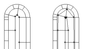
In the left drawing, you see that the ribbons on the way towards the hairpin, do not overlap with the ribbons coming from the hairpin. On the right drawing, you can imagine that in mid-corner, an external camera doesn't know what to do anymore, and this becomes clearly visible as some mixed-up scenery parts.Therefore, you should avoid using scenery like in the right drawing, unless you know very well what you're doing.
In the TE 1.6.7 there is a good representation of the distance a ribbon has to the track. So this will certainly point you to situations where the ribbons make the error described here.
3.4 Scenery on the outside of corners
On the outside of corners, scenery is usually not that much of a problem. Some things to note, though. Fisrt of all, ribbons on the outside of a corner are much longer than on a straight section. That means, that the textures applied to ribbons in a corner, appear very stretched. Therefore, you should always define textures for straight sections and curves separately. This problem is best visible with trees, on straights you can have one texture per 4 length-units, while in the corner you need twice as much to get the same type of trees.Secondly, a graveltrap on the outside of a corner means that the verges are a lot further form the track than elsewhere. That means, you also have to move your scenery backwards, as otherwise, you will have some scenery overhead when you accidentally drive through the graveltrap.
3.5 Scenery Shortcutting using Scenery5 and 0xC0/0xC1
By default, the scenery ribbons follow the corners in the track. You can see that clearly on, for example, the Hockenheim track where the grandstands have the same curvature as the track. Now sometimes, you want to let the scenery follow a straight line from one point to the other. This can be done by adding a Scenery5 command. You can see a close analogy between adding a scenery5 command in a certain tracksection, and clicking the "bridge fence" checkbox. One counts for the ribbons, the other one for the fences. Note that you have to specify in the Scen5 cmd to which ribbons this effect should be applied.Another way to create a similar (yet slightly different) effect is by using an 0xC0 or 0xC1 command, instead of the 0xAF command. By doing that, you refrain from defining the scenery on both sides of the track, and choose to define only one. I will make a drawing to clearify this:
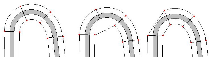
I would like to emphasize I drew the ribbons curved, like they appear
in the game, but NOT like they appear in the Trackeditor.
On the left, you see a normal defined scenery, with 0xAFs and 0xB8s.
In the middle, you see the real situation when one of the 0xAFs is replaced
with a 0xC0. This command defines only the left side, making the game connect
the rightside ribbons without taking this 0xC0 and it's accompanying 0xB8
into account.
On the right side, you see that the first curved section has a scenery5,
0xBA command. That causes the ribbons to go straight WITHIN that particular
tracksection.
Note that the scenery5 command is a SWITCH that can be set for some part of the track, and some ribbons using the location code. There is also another command that influences this setting in some way, I believe 0xC7 or 0xC6. You are warned!
The work on Circuit Ultima set me on this. In the Casino corner,
there is a building to the right, made of ribbons. You should examine this
building closely, it's extremely complex, and cost me a few hours to understand.
In t25, the second scen1 (offset 1) defines the right side of the
facade of the building. After that, there follow in t27 three scenery-lefts.
Then in t29, there is a scenery-left (0xC0) , followed by a 0xAF. At this
moment, 4 Ts later and over 4 scenery-lefts, the building-definition continues.
In the meantime we have rounded a 120 degree righthander. Yet, the building
is flat. That's quite logical, as I can't make a guess WHICH curvature
should be taken, if you have crossed four tracksections. That let me to
the conclusion that it would make more sense if it was a straight line
from one definition to the other.
3.6 Multiple Scenery Commands in one tracksection
Note that this is not well supported in the TE. The TE only shows the first scen1 cmd of a section, and the following ones not. This will be amended (and partially already is), in newer verions of the TE.In the meantime, from TE1.6.9 or so, the multiple-scenery cmds is very well implemented in the trackeditor, and this should no longer lead to any problems. It is just good to know that it is possible to use more scen1's in one TS. They all must have a 0xAF or 0xC0/1 before them ofcourse, otherwise things will get mixed up. The offset that you put in the 0xAF/0xC0/1 is used by the 0xB8 to define where it's located. This particular thing is not yet implemented in the TE, and all scenery definitions appear to have taken place at the start of the TS.
3.7 Switching Ribbons On and Off
Just defining the basic structures is not enough to see nice scenery. The ribbons can be switched on and off using different commands. This way, you can generate different effects.The main way to switch ribbons on is using the Scenery4 (0xD9) and Scenery
2 (0xB9) commands.
The way to switch an individual ribbon off, is using the 0xB0 command.
The values in the arguments of these commands indicate a texture location,
of type <B>.
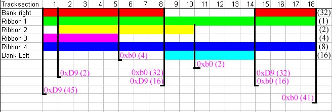
In this picture you see how it works. The bars indicate whether a ribbons
should be switched on or off at a particular tracksection. You should have
a picture like this in your head, when you're making the scenery. Now,
you see on this picture where you have to insert the commands in order
to get the commands switched on and off. Between bracketts, I have placed
the appropriate a2 value of the particular command. On the right you see
the <B> type location codes, directly from the location-table
in 2.2. Note that every command has to be inserted at the first tracksection
in which it should work. For example, the first command should be inserted
in t1, and the last one in t19 (not drawn in the picture)
Paul Hoad has made a drawing in the TE just like this, so you can monitor where your ribbons go in case you miss one. It is accesible by clicking a 0xB8 in the pitlane, or on the track.
When you think of switching a ribbon to another side, you have to switch a ribbon off, and on again a little later. Then, you have an 0xb0 for that particlar ribbon, and an 0xD9 again in (for instance) the following tracksection.
Switching a ribbon to another side therefore usually implies to switch
a ribbon off, and on again. To know which ribbon you have to switch off
can be figured out, but as an extra service I put a table here. Note that
the back-switching implies the temporarily switch-off of the same ribbon
as the switch-forward.
| ribbons to right | 0 | 1 | 2 | 3 | 4 |
| 0 | X | 1 | 1,2 | 1,2,3 | 1,2,3,4 |
| 1 | 1 | X | 2 | 2,3 | 2,3,4 |
| 2 | 1,2 | 2 | X | 3 | 3,4 |
| 3 | 1,2,3 | 2,3 | 3 | X | 4 |
| 4 | 1,2,3,4 | 2,3,4 | 3,4 | 4 | X |
By the way, this method does not work always. It's partially an unknown section of scenery-editing, and I can't really help you much here. Trial and error is the thing, unfortunately. One way to help you is this: Apply in the trouble-zone (temporarily) a good recognizable, and different texture to all ribbons, like water or gravel. This way, you can easily spot in the game which ribbon# gives the problem.
3.8 Lighting and Darkening of Ribbons
This is done with the scenery7, 0xCD command. It defines the lightevel for a particular ribbon (or fence or verge). This can be used for instance to darken the inside of a tunnel. Another use is to lighten the ribbons of a house. Usually the houses are quite brown due to the sun being at the other side, therefore it becomes too brown. Lighting it gives it a fresh, beautiful look.This command does not apply to objects. For objects, there are other
commands that define the lightlevel, but these are still unknown.
3.9 Transitions
This is by far the most difficult part of making extensive scenery-structures, such as can be found on Tunneltrack and StuwLake. For every other structure, you have to come up with a different solution to make the transistion from a mountanous part to a forest of trees look good and natural. But some things can be said about it, and may give you a hint of the path to follow.Normally, if you just change the number of ribbons to a side, and adapt
the 0xB8 values, there will be a piece of scenery crossing the track. Sometimes,
though, you are lucky and are bug-free. But if you're not, you obviously
have to switch off a ribbon for one TS. The problem it, to determine which
one. A method that works is to put a different texture to each ribbon,
and then you can easily spot which one is crossing the track. Then you
know which one has to be switched off. A bit of a trial and error, but
I can't think of anything else right now.
Chapter 4
Structures and Formations.
The objective of this chapter is to make clear how certain features on the track are build of banks and ribbons. This may not be too obvious on first look, but after reading this chapter it should be clear.If you come up to a certain structure that you wonder about, let me know, and I can include it.
4.1 Basic hill
The basic hill is made out of ribbons that have a decreasing slope, to get the effect of depth. Most of the time, one ribbon and the bank is enough to make it look good.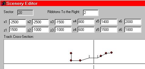
The hill is the right side of the track. Note that the slopes of the bank and the first ribbon are equal, the split is made because of texturing- use.
4.2 Walls
Walls are made in the same way as hills, although now the end of the bank (usually) has the same X-value as the start of the bank. Because the start of the bank is determined by the width of the track and the verges, it is sometimes difficult to get the wall totally straight up. For a "typical tracksection", a Xvalue of 500 might work. If you drive past it once in the game, you'll notice immediately if it's vertical or not.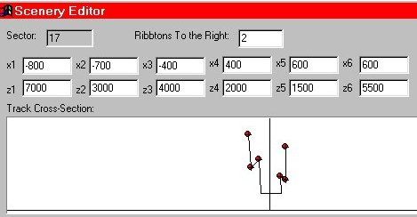
Both sides have a wall here. Note the vertical banks, they form the walls here, but that is not necessary. Also, the right side seems to hang over the track a little. This may be just the picture drawn in the TE, as it's also difficult for Paul to see the relation between trackwidth, verge-width and the scenery-coordinates.
The thing that makes a wall look like a real wall is ofcourse the texture. But I initially decided that texturing commands and uses are outside the scope of this tutorial. If anyone feels it should be included, let me know.
4.3 Basic trees
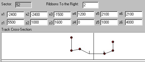
Here you see trees on both sides of the track, the vertical ribbons (12 and 13). The right side has a small hill, on top of which the trees are build. On the left side, this hill recedes a little near the trees, giving an increased idea of depth.
4.4 Two lines of trees
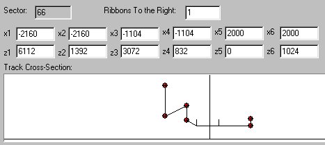
Here you see the Fagnes curves on the original Spa-Francorchamps. There are three vertical ribbons, all carrying tree-textures. The two to the left are somewhat special; you can see the large, outer tree-line above, and behind the near, inner line of trees. This gives an impression of a tree-covered hill. Note that the ribbon 13 here is purely a connection-ribbon between the tree-lines, that is best switched off. Else, you will see some texture on top of the trees which is usually very ugly.
4.5 Cliffs
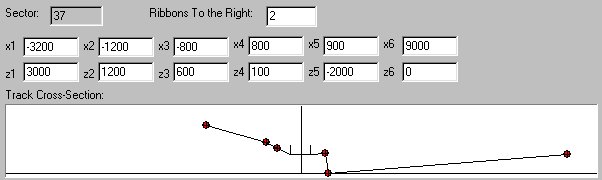
I think it's nice to drive along a lake with a F1 car, (it's however not very realistic). But, here you see how that lake could be build. On the right side, you go from the fence first a little horizontal, giving some room to place trees or adverts. Then, the scenery drops to the level of the lake, with an almost-vertical ribbon. This one is best covered with a rocky texture. Now, the lake is build very wide, and rises from the level of the cliff (z5 indicates the height of the cliff) again to zero, to enable a good attachment of the lake-ribbon to the horizon. If the lake is horizontal, there will be a gap between the level of the lake and the horizon, while you may want to make it look like it's never-ending.
4.6 Rocks
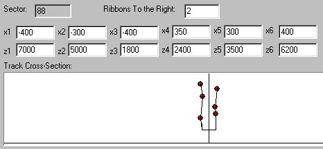
To make a nice canyon, bend the ribbons a little like this. Make a new scenery1 cmd frequently, every 25 trackunits minimum. Also, make it a little erratic, to give the raw rocks-image. A rocky texture is also a good idea.
4.7 Grandstands
Grandstands are actually quite like hills, although with usually a different texture, and much more straight. The idea is, like the house in the next chapter, to make the sides perpendicular to the track. In this case however, the "roof" of the house is made larger, and the structure is made much longer. In the drawing you'll find some basic cut-throughs of stands, with or without roof, or multiple layers. Ofcourse, it's most fun to make one up yourself.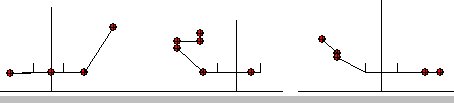
Left you see the grandstand used in the original Brazil track, before
start/finish. It's just a plain slope, covered with crowd-texture. The
main advantage of using ribbons for grandstands, over objects, is that
you can easily curve the grandstands. That can be seen too on the original
HockenheimRing, where the grandstands are curved for a long way. In the
middle you see the grandstands that are build there, where there is a little
roof build. The dimensions are a bit exaggerated, for clearity reasons.
On the right you see a made-up grandstand, which you can find on the Elkhart
Lake track (by Romeo and me), where the stands consists of two rows, clearly
set apart by a vertical ribbon with another texture. These places are ideal
for some advertisements.
4.8 Basic house
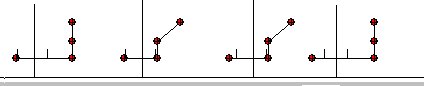
An impression of a house consistes of two side-planes and a front-plane. These planes should be perpendicular to each other. In GP2 that's impossible to make using ribbons, and therefore we will use an approximation. As an example, I will use the house that's build in Tunneltrack.This house is build, using a particular order in which the scenery1 cmds are formed. First, you have a basic rock which is a little bend back at the bottom. Then, you bend the lower ribbon toward the track, and vertical, within one tracklength unit. That makes this plane almost perpendicular to the track. Now, you make another scen1 cmd some 15 units away, with the same values. This makes the front-facade of the house. Finally, you make it bend backwards again, within one length-unit, to get the second side-plane. I will make drawings of this, and you should read it as a follow-up, so try to follow each ribbon, and see what it does.
4.9 Gallery
Not to be done.4.10 Tunnels
Jason Sinnbeck describes it like this:2 RIBBON-PER-SIDE TUNNEL TUTORIAL
Having difficulties figuring out how to create a nice tunnel entrance & exit?Perhaps this short tutorial can help you. The following is a basic description
of some values & commands that can be employed as a base to make a nice tunnel
inside a low-ish hill.
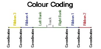
The illustrations used in this tutorial show the ribbons and banks colour
coded so as to make it simpler to understand which ribbon is doing
what.
Here is the key to the colour coding.
< tunnel_0.jpg >
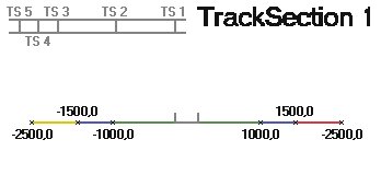
OK. Lets get started. In the diagram below we are locating the ribbons
to form
the outer bases of our hill. Hence the large X values to take them
out a long
way out from the track, and the absence of height (all Y values = 0)
since our
hill will naturally be starting from ground level.
< tunnel_1.jpg >
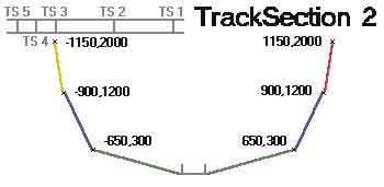
With the track section 2 scenery command we start to raise the ribbons
and bring
them back towards track, thus creating the start of our hill.
Note: For the values used in this tutorial, track sections 1 &
2 should be in
the order of 10 units length to give a nice result.
< tunnel_2.jpg >
The scenery command at the start of TS#3 is really just a continuation
of the
trend set by TS#2 scenery values. Remember that the rate of rise (gradient)
of the hill through TS #1 is controlled by the values at the start
of TS#2,
and that TS#2's gradient is controlled by TS#3's values. The reason
that this
had been pointed out is that if you study the Y values between the
TS#2 command
and the TS #3 command you will notice that about 55-60% of the rise
of the hill
occurs DURING TS#1, and TS#2 is left with about 40-45% of the remaining
height
that makes up the Y co-ordinates total value at TS#3. This gives our
hill a
"rounding off" effect.
Remeber that both TS#1 & #2 have to be of a similar length for
this to be valid.
< tunnel_3.jpg >
You could leave out TS#2 altogether and just have a straight hill rise
to the
start of TS #3. Alternately, you could put more sections in for an
even nicer
rounding effect on the hill side. Whatever you feel like!
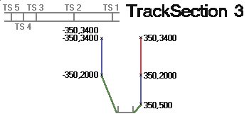
You have no doubt noticed that Ribbon 3 finishes TS#2 (i.e starts TS#3)
at the
same co-ordinates as ribbon 4. That is because we have to turn ribbon
3 off for
it's journey through TS#3 as it must cross the track. If it was still
higher
than Ribbon 4 we would see it suddendly stop when turned off. Not very
pretty.
So we piggy-back it briefy on ribbon 4 to hide it's changing of state.
To this extent, TS#3 must have an 0xb0 command to turn ribbon 3 off.
The section offset a1 will be 0, and the location code for a2 will
be 4.
Also, TS#3 is typically very short. Just one length unit is normal.
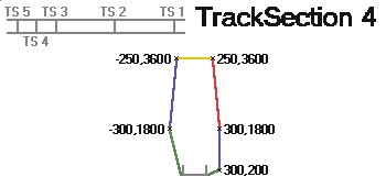
Now to the start of TS#4. Ribbon 3 has crossed the road and is connected
to the
top of ribbon 2. Time to turn it back on. The simplest way is to just
throw in
an 0xd9 with an a1 value of zero, and with a2 = 63. This turns 'em
all on.
Also notice that there has been a slight increase in the hill's height
again.
This is optional, but I think it looks a little better this way.
< tunnel_4.jpg >
TS#4, like TS#3, is also usually just 1 unit in length.
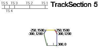
And now last, but by no means least, we reach TS #5; the actual start
of our tunnel.
The values used here are simply copied throughout the length of the
tunnel.
< tunnel_5.jpg >
During TS#4, ribbons 2 & 4 have been lowered, taking the still-connected
ribbon 3
with them. This gives us the front face of the hill that becomes the
roof of the
tunnel in TS#5 once lowered.
When you get to the exit, it is simply a reverse of the entry (except
that you will
still have the 0xb0 before the 0xd9 of course) and then you can adjust
the values to
achieve the desired result. For example, the ficitious Eagles Nest
circuit (available
from Sjon's) shows a nice version of an exit that becomes a hillside
spectator mound
on one side.
The only other thing to mention here is that the track verge values
used are 15. If
you go for a tight tunnel with small verge values, say about 12 or
less, you may
notice that you have flags being waved by a marshall's arm which is
protruding from
the wall on the side of your tunnel. Ghost marshalls perhaps? Kinda
spooky, and not
too reassuring for Schuey, Fissi, Damon & co as they blast on through....
Chapter 5
Addie's Special-Request Section
In this section some things about subjects that belong sideways to scenery will be said. I will make some notes about the use of the 0xBC command, as it is closely related to ribbons. The part about view-distances is a bit of a repetition of the commands-library, but more integrated in the scenery-stuff.View-distances
The game determines how much of the track need to be drawn in front, by using commands. This command is NOT a definition of the "distance the beam of light shines in front of the car", but more of an one-time placement of scenery, where you drive on to. That means, you have to place these commands more than once on the track. Best bet is to place the commands in the middle, or just before the corner. The view-distance value should be put then, so that the whole straight following the corner is viewed when exiting the corner. So for a long straight, you need to give a high view-distance in front, and for a shorter one, a lower value should be allright. The trade-off here is between the distance in front you see (and need) and the processor-occupancy, because longer view-distances give the computer more to think about, and thus higher occupancy. The maximum value you can safely enter is 255, you are advised to not go over this limit.The commands used for view-ahead are 0x81 and 0xBE. Exactly why there are two commands remains unknown, but just remember to put an 0x81 AND and 0xBE in the middle or before every corner. It is advisable to use the same distances in both commands, although not neccesary. For the location code, I would say use 63, but maybe 48 works just fine.
Maybe the best way to check the "view distance behind" commands is by driving the track the wrong way around. Then, you can immediatly spot that for a long straight, the view-command is placed AFTER the straight, not before. So build them in exactly the same way as the view-distances in front, when thinking of driving the wrong way. Use the commands 0x82 and 0xBF.
The units of these commands is the same as the tracklength-unit so you can calculate which values you need by looking at the length of the straight following your command. Most of the time, values around 150 are enough.
Appendix
A1. Frequently Asked Questions
1) I have clicked "Remove Scenery" but now I want scenery on my track!
This really is no problem anymore!- Insert a lot of Scenery3 (0xAF) and Scenery1 (0xB8) commands,
before and after each corner at least. Make sure the Scenery3 command comes
before the Scenery1 command! To do this efficient, insert a scenery3 command
in the first TS, "copy" it, and "paste" it at strategic places. Then, insert
a Scenery1 command at TS0 and fill in some decent values. Now, "copy" this
command, then paste it at exactly the same locations as you put the Scenery3
cmds in. Don't miss any, and don't put in too many. Next, include a scenery4
[0xD9] command [a2=63] in the first TS, like told above. Then, remove all
the influencing commands as explained in Ch3, Guideline.
2) Can you make the scenery for my track?
No, of course not! Then it would become my circuit, and no longer yours! It would cost me hours and hours, and I'd rather spend those on a track of my own. Only in very special cases, like when it's a really good track, I will consider making scenery for it.3) Where can I find the Scenery-tutorial?
Well, you already have it... But you can usually download the most recent version athttp://www.sepa.tudelft.nl/webstud/426090/index.htm
The tracks I build are also available there.